Introduction to PolyWorks Universal 3D Measurement Software PlatformPolyWorks is the premier comprehensive enterprise solution. From the measurement plan of the design and manufacturing team, to the measurement task execution of the quality control team, to the enterprise-wide 3D measurement data sharing, PolyWorks supports the 3D measurement work of all industrial manufacturing organizations. Process. | |
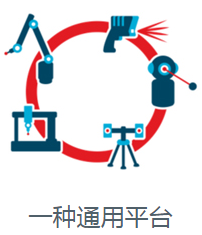 | Compatible with all 3D measurement equipment, using a common workflow to perform all inspection tasks. |
 | Optimize the management of your existing database and digitally connect the product engineering and manufacturing teams. |
 | Promote teamwork at each stage of the product development process. |

Introduction to PolyWorks|Modeler™PolyWorks|Modeler™ is a comprehensive reverse engineering software solution that can extract CAD entities—curves, surfaces, parametric sketches, and prismatic features—from the polygonal model of the scanned workpiece in the best way, as your professional CAD The starting point for modeling solutions. |
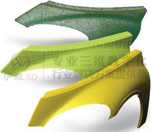
Triangulation Modeling-From Triangulation Model to Manufacturing The first step of reverse engineering involves converting the scanned point cloud into a polygonal model, also called "meshing". precise Data processing techniques can be applied to the most primitive point cloud in the gridding stage, such as smoothing points or sampling based on curvature. The final result is more compact, more accurate and less noise than the original. Many industry applications can directly use the triangulation model. For example, it can either directly process the triangular model and use a 3D printer to manufacture it, or import it into aerodynamic simulation software for analysis. PolyWorks|Modeler provides two polygon editing tools to generate the polygonal models required for these applications: • The first set of tools is designed to repair and optimize defective scan data geometry. For example, it may be necessary to insert a new triangular surface in the unmeasured area to create a complete surface. • Another set of tools provides CAD operations on the polygonal model, such as stretching, offsetting, rounding, or Boolean operations. | |
| Surface modeling-create CAD-friendly free-form surfaces Professional CAD/CAM solutions usually do not provide 3D modeling tools for triangular models. A common method to convert the scanned object surface to CAD/CAM software is to fit the NURBS surface mesh on the triangularized model established by the scanned point cloud. NURBS surfaces are ideal mathematical descriptions of free-form surfaces, and they are CAD/CAM friendly. PolyWorks|Modeler proposes an intuitive surface generation method. Firstly, curves are placed on the triangular model, and then automatically intersected to generate four-sided or N-sided NURBS patches, and use NURBS patches to control the fitting of the continuous mesh of NURBS surfaces. The fitted surface can be exported to your favorite CAD/CAM program for further appearance surface processing. PolyWorks|ModelerNURBS surface technology provides a significant balance between man-hours and surface quality due to: • Intuitive curve correction method and continuous curvature curve • The best NURBS surface fitting engine on the reverse engineering market, reflected in quality (precision, smoothness and continuity) In terms of flexibility (trimmed surfaces and T-shaped knots, a two-step matching process based on curvature, from mixing and matching surfaces to existing CAD models, realizing the possibility of localized CAD reconstruction) • Control the G2, G1, or G0 continuity of the boundary of the NURBS patch • Automatically fit G2 surface to NURBS patch area with rectangular topology structure |
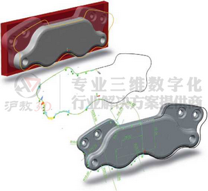
Solid modeling-build solid CAD models from optimized geometric entities. The principle of PolyWorks|Modeler solid model includes optimizing the geometric entities extracted on the scanned polygonal model, and then transforming these extracted entities into all feature-based solid CAD models, ensuring parametric, associative, and fully editable solid models . A basic modeling workflow is a parametric 2D sketch. 2D sketches are composed of two-dimensional entities, such as arcs, lines, circles and Curve, defined on a plane embedded in 3D space. In solid modeling software, the sketch creates the basic features of the solid by performing extruding, rotating, scanning or lofting operations. Create a sketch in the following way: 1. Define a sketch plane 2. Calculate the sketch contour by cutting the section or extracting the contour edge from the scanned model 3. Anchor and fit the sketch entity according to the sketch contour Parametric sketches can be converted to solid CAD modeling software using plug-ins (SolidWorks, Inventor, etc.) or common formats (IGES). Then, you can combine the sketch and the fitted NURBS surface, use the size from the fitted prism geometry, and then directly design the solid model you want in the professional CAD software you are most familiar with. With PolyWorks|Modeler, solid modeling has unlimited possibilities. Use your creativity to achieve it. |
|


